SVG’s provide:
Instantaneous, stepless reactive power compensation which results in power factor correction (both leading and lagging).
Voltage support which results in higher process reliability, longer equipment lifetime, and reduction in energy losses while also decreasing the load on electrical infrastructure, dynamically balancing electrical systems, and ensuring compliance to a range of Australian Standards.
Key Benefits
- Save Money
Improving power factor lowers kVA demand, meaning network charges are reduced significantly. Enginuity Power Solutions has numerous case studies where this is in the tens of thousands of dollars per year. - No on-going maintenance
There are no ongoing maintenance costs. Due to the device having no spare parts such as contactors and/or capacitors that require replacement so long as the device is kept clean, there is no maintenance to carry out. - More space is freed up on the electrical network
Reduction in demand means more ‘space’ is created/freed up on the electrical network. As production increases in plants, more infrastructure is installed on different sites, more electrical load is required. In a lot of instances, improving power factor results in large amounts of capacity being freed up on existing infrastructure meaning expensive upgrades can be avoided. - Dynamic load balancing is taken care of
The SVG balances phase currents, reducing the peak current and saving you money on your electrical bills.
How SVGs Works
What Is Power Factor?
Power Factor is a measure of how effectively incoming power is used in your electrical system and is defined as the ratio of Real (working) power to Apparent (total) power.
Real Power (KW) is the power that actually powers the equipment and performs useful, productive work. It is also called Actual Power, Active Power or Working Power.
Reactive Power (KVAR) is the power required by some equipment (eg. transformers, motors and relays) to produce a magnetic field to enable real work to be done. It is necessary to operate certain equipment, but you do not see any result for its use.
Apparent Power (KVA) is the vector sum of Real Power (KW) and Reactive Power (KVAR) and is the total power supplied through the power mains that is required to produce the relevant amount of real power for the load.
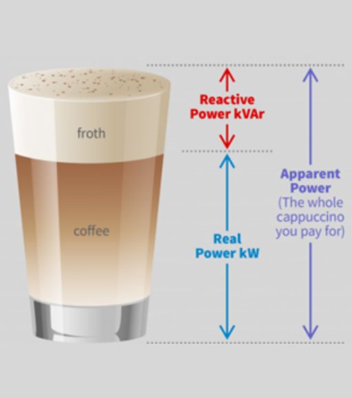
The power factor is the ratio between Real Power and Apparent Power. It is expressed as a value between -1 and 1 and can be either inductive (lagging) or capacitive (leading). If the power factor is 1, then all the power supplied is being used for productive work and this is called ‘unity’.
![\[ Power Factor = \frac{Real Power (kW)}{Apparent Power (KVA)} = \frac{Coffee}{Coffee + Foam} \]](https://enginuityps.com.au/wp-content/ql-cache/quicklatex.com-d869398972ba50f4463a8cfbdb957071_l3.svg "Rendered by QuickLaTeX.com")
Therefore, for a given power supply (KVA):
The more foam present (the higher the percentage of KVAR), the lower the ratio of KW (coffee) to KVA (coffee plus foam). Thus, the poorer the power factor.
The less foam present (the lower the percentage of KVAR), the higher the ratio of KW (coffee) to KVA (coffee plus foam) and the better the power factor. As the foam (or KVAR) approaches zero, your power factor approaches 1.0 (unity).
How SVGs Improve Power Factor
Traditionally, switched capacitor banks have been utilised to combat issues relating to power factor. These switched capacitor banks were designed decades ago when the electrical systems they were operating in were much simpler and consisted of linear loads (i.e. loads that did not contain large amounts of electronic devices).
A modern electrical system contains a number of large electronic loads due to the adoption of energy efficient equipment such as LED lighting and variable speed drives for electric motors, uninterruptible power supplies (UPS) and switch mode power supplies in electronic equipment such as computers.
These non-linear, dynamic loads operate in principle by the loads being switched extremely quickly, resulting in the traditional capacitor based compensation system being unable to maintain an effective compensation set-point. This results in the load being either under, or over compensated.
The Modern Day Solution: SVGs
An SVG works as a controlled current source providing any kind of current waveform in real time. When the load generates inductive or capacitive current, it results in equilibrium between the current and voltage waveform.
An SVG detects the phase angle difference and injects in real time leading or lagging current into the electric power systems, making the phase angle of the current almost the same as that of the voltage, bringing fundamental power factor to unity.
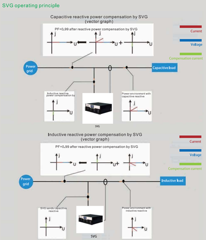
A simple scenario of 1 – 1 = 0 in that rather than paying the utility for the reactive power, you simply generate your own and inject it into the grid.
Traditional Switched Capacitor Banks System Vs. Static Var Generator
| Performance | Cap Bank System | SVG |
| Operation | Detects load current in real time on 1 of the three phases only. Compensation to all 3 phases is based off this measurement meaning that stepped compensation is provided to all phases regardless of the requirement. | Detects load current on all three phases. Provides dynamic, stepless compensation to all three phases |
| Method of compensation | Switched capacitor banks provide compensation in fixed steps (6.25kVAr, 12.5kVAr, 25kVAr, 50kVAr) | Dynamic compensation which is stepless |
| Power Factor Correction | Capacitor banks can only rectify issues with inductive loads. Constantly over or under compensating | Corrects simultaneously leading and lagging power factor (inductive or capacitive) from -1 to +1. |
| Load Balancing | Cannot correct load unbalance | SVG can balance phase currents |
| Harmonics | Capacitors are not tolerant to system harmonics and | SVGs can operate in environments with high system harmonic levels (up to 20% THDV) |
| Response Time | From 20ms to 40 seconds! This delay coupled with the stepped response means they are always under or over compensating | Analyses load data and responds in <15ms and a dynamic response time of <50μs – meaning response is real-time and avoids under or over compensation |
| Size and Space | Due the stepped nature of compensation, more smaller stepped sizes are required to suit the changing load requirements. As such, systems are oversized to accommodate. | The compensation capacity of SVG’s is the same as the installed capacity meaning the capacity of the SVG is generally 20-30% less than that of a capacitor bank. |
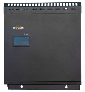
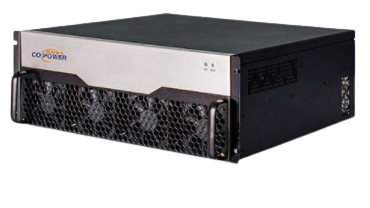
| Mounting Arrangements | Large cabinets are required to house the switched capacitor bank infrastructure | SVG’s are available in both rack mount and wall mount options. Units can be simply be parallel connected to obtain the compensation capacity required. |
Enginuity Power Solutions’ SVG Product
When you choose our SVG product, you are choosing the most simple, turnkey solution to improve your power quality and meet Australian Standards.
To set you up with the solution for your specific application, all we need is some very basic information that you or any maintenance electrician can easily gather. Our team then takes this data and, using a series of automated calculators, we can quickly match you with the right solution. This cuts out the need for on-site studies by engineering teams or specialist contractors which saves you time and money.
We will then ship out the product with all mounting configuration, current transformers, cabinet, and all other infrastructure required to fit on site. Commissioning and technical support is provided throughout the installation process.
Our SVGs are certified for the Australian market and tested to the following standards:
IEC 61000-6-2:2019
IEC 61000-6-4:2019
IEC 62477-1:2012
**Certificate of Conformity EMC issued by TUV Rheinland
")
")
")
")
")